Tuesday 25 January 2022

Verilog Code for Carry Lookahead Adder


Gate Level Modelling

module carrylookahead(a,b,cin,sum,cout);

input a0,a1,a2,a3,b0,b1,b2,b3;

input cin;

output sum0,sum1,sum2,sum3;

output cout;

wire p0,p1,p2,p3,g0,g1,g2,g3,x0,x1,x2,x3;

wire c1,c2,c3;

xor g1(p0,a0,b0);

xor g2(p1,a1,b1);

xor g3(p2,a2,b2);

xor g4(p3,a3,b3);

and g5(g0, a0,b0);

and g6(g1, a1,b1);

and g7(g2, a2,b2);

and g8(g3,a3,b3);

and g9(x0, p0,cin);

and g10(x1, p1, c1);

and g11(x2, p2, c2);

and g12(x3, p3, c3);

xor g13(s0, p0,cin);

xor g14(s1, p1, c1);

xor g15(s2, p2, c2);

xor g16(s3, p3, c3);

or g17(c1,g0,x0);

or g18(c2, g1, x1);

or g19(c3,g2,x2);

or g20(cout, g3,x3);

endmodule


Data Flow Level Modelling

module carrylookahead(a,b,cin,sum,cout);

input a0,a1,a2,a3,b0,b1,b2,b3;

input cin;

output sum0,sum1,sum2,sum3;

output cout;

wire p0,p1,p2,p3,g0,g1,g2,g3,x0,x1,x2,x3;

wire c1,c2,c3;

p0 = a0^b0;

p1 = a1^b1;

p2 = a2^b2;

p3 = a3^b3;

g0 = a0&b0;

g1 = a1&b1;

g2 = a2&b2;

g3 = a3&b3;

c1 = go|(po&cin);

c2 = g1|(p1&c1);

c3 = go|(p2&c2);

cout = go|(p3&c3);

sum0 = p0^cin;

sum1 = p1^c1;

sum2 = p2^c2;

sum3 = p3^c3;

endmodule

Verilog Code for 4 to 2 Priority Encoder


Gate Level Modelling

module 4to2priorityencoder(y0,y1,y2,y3,a0,a1);

input y0,y1,y2,y3;

output a0,a1;

wire x0,x1;

not g1(x0,y2);

or g2(a1,y3,y2);

and g3(x1, x0,y1);

or g4(a0, x1, y3);

endmodule


Data Flow Level Modelling

module 4to2priorityencoder(y0,y1,y2,y3,a0,a1);

input y0,y1,y2,y3;

output a0,a1;

assign a1 = y3| y2;

assign a0 = (~y2 & y1) | y3;

endmodule


Behavioral Level Modelling

module 4to2priorityencoder(y0,y1,y2,y3,a0,a1);

input y0,y1,y2,y3;

output reg a0,a1;

always @(y)

begin

case({y3,y2,y1,y0})

4'b0001: begin a0=0; a1 = 0; end

4'b001x: begin a0=1; a1 = 0; end

4'b01xx: begin a0=0; a1 = 1; end

4'b1xxx: begin a0=1; a1 = 1; end

endcase

end

endmodule

Monday 24 January 2022

Anna University resived Exam Schedule


Anna University Revised Exam Schedule

Anna University Sem Exam Instructions


Anna University Semester Exam Instructions 

Verilog code for 4 to 2 Encoder


Gate Level Modelling

module 4to2encoder(a,b);

input [3:0]a;

output [1:0]b;

wire x0,x1,x2,x3;

xor g1(x0,a[3],a[2]);

not g2(x1,a[0]);

not g3(x2,a[1]);

not g4(x3,a[2]);

and g5(b[1], x0, x1,x2);

xor g6(x4, a[3], a[1]);

and g7(b[0], x1, x3, x4);

endmodule


Data flow Level Modelling

module 4to2encoder(a,b);

input [3:0]a;

output [1:0]b;

assign b[1] = (a[3]^a[2]) & (~a[1]&~a[0]);

assign b[0] = (a[3]^a[1]) & (~a[2]&~a[0]);

endmodule


Behavioral Level Modelling

module 4to2encoder(a,b);

input [3:0]a;

output reg [1:0]b;

always @ (a)

case({a})

4'b0001: begin b[0] = 0; b[1] = 0; end

4'b0010: begin b[0] = 1; b[1] = 0; end

4'b0100: begin b[0] = 0; b[1] = 1; end

4'b1000: begin b[0] = 1; b[1] = 1; end

endcase

end

endmodule

Verilog code for 4-bit Ripple Carry Adder


Full adder

module fulladder(a,b,cin,s,cout);

input a, b, cin;

output s, cout;

wire x,y,z;

xor g1(x,a,b);

and g2(y,a,b);

and g3(z, x,cin);

xor g4(s, x,cin);

or g5(cout, y, z);

endmodule


4-bit Ripple carry adder using Full adder

module ripplecarryadder(a,b,c,sum,cout);

input [3:0]a,b;

input cin;

output reg [3:0]sum;

output cout;

wire [2:0]c;

fulladder f1(a[0],b[0],cin,sum[0],c[0]);

fulladder f2(a[1],b[1],c[0],sum[1],c[1]);

fulladder f3(a[2],b[2],c[1],sum[2],c[2]);

fulladder f4(a[3],b[3],c[2],sum[3],cout);

endmodule

Sunday 23 January 2022

Verilog Code for magintude comparator


Gate Level Modelling

module comparator(a,b,c,d,e);

input a,b;

output c,d,e;

wire p,q,r,s;

not g1(p,a);

not g2(q,b);

and g3(c,p,b);

and g4(r, p,q);

and g5(s, a,b);

or g6(d, r,s);

and g7(e, a,q);

endmodule


Data Flow Level Modelling

module comparator(a,b,c,d,e);

input a,b;

output c,d,e;

assign c = ~a &b;

assign d = (~a&~b)|(a&b);

assign e = a&~b;

endmodule


Behavioral Level Modelling

module comparator(a,b,c,d,e);

input a,b;

output reg c,d,e;

always @(a,b)

begin

case({b,a})

2'b00: begin c = 0; d=1; e=0;end

2'b01: begin c = 0; d=0; e=1;end

2'b10: begin c = 1; d=0; e=0;end

2'b11:begin c = 0; d=1; e=0;end

endcase

end

endmodule

Verilog Code for 2 to 4 Decoder


Gate Level Modelling

module 2to4decoder(a0,a1, d0,d1,d2,d3);

input a0,a1;

output d0,d1,d2,d3;

wire s,t;

not g1(s,a0);

not g2(t,a1);

and g3(d0, s,t);

and g4(d1, a0,t);

and g5(d2, s,a1);

and g6(d3, a0,a1);

endmodule

Data flow Level Modelling

module 2to4decoder(a0,a1, d0,d1,d2,d3);

input a0,a1;

output d0,d1,d2,d3;

assign d0 = ~a0 & ~a1;

assign d1 = a0 & ~a1;

assign d2 = ~a0 & a1;

assign d3 = a0 & a1;

endmodule

Behavioral level Modelling

module 2to4decoder(a0,a1, d0,d1,d2,d3);

input a0,a1;

output reg d0,d1,d2,d3;

always @(a0,a1)

begin

case({a1,a0})

2'b00: begin d0 = 1; d1 = 0, d2 = 0; d3 = 0; end

2'b01: begin d0 = 0; d1 = 1, d2 = 0; d3 = 0; end

2'b10: begin d0 = 0; d1 = 0, d2 = 1; d3 = 0; end

2'b11: begin d0 = 0; d1 = 0, d2 = 0; d3 = 1; end

endcase

end

endmodule

Verilog Code for Demux


Gate Level Modelling

module demux(a1,a0, Din, y3,y2,y1,y0);

input a1,a0,Din;

output y3,y2,y1,y0;

wire s,t;

not g1(s,a0);

not g2(t,a1);

and g3(y0, s,t,Din);

and g4(y1, t, a0, Din);

and g5(y2, a1, s, Din);

and g6(y3, a0, a1, Din);

endmodule


Data flow Level Modelling

module demux(a1, a0, Din, y3, y2, y1, y0);

input a1, a0, Din;

output y3, y2, y1, y0;

assign y0 = ~a0 &~a1 & Din;

assign y1 = a0 & ~a1 & Din;

assign y2 = ~a0 & a1 & Din;

assign y3 = a0 & a1 & Din;

endmodule

Behavioral Level Modelling

module demux(a1, a0, Din, y3, y2, y1, y0);

input a1, a0, Din;

output reg y3, y2, y1, y0;

always @ (a0,a1,Din)

begin

case({a1,a0})

2'b00: begin y3 = Din; y2 = 0; y1 = 0; y0= 0; end

2'b01: begin y3 = 0; y2 = Din; y1 = 0; y0= 0; end

2'b01: begin y3 = 0; y2 = 0; y1 = Din; y0= 0; end

2'b01: begin y3 = 0; y2 = 0; y1 = 0; y0= Din; end

endcase

end

endmodule

Saturday 22 January 2022

Anna University 2021 - 2022 ODD semester Time Table


 2021 - 2022 ODD sem Exam Time Table

Verilog code for 2:1 MUX


Gate Level Modelling

module 2to1mux(y,s,D0,D1);

input D0,D1,s;

output y;

wire sbar,p,q;

not g1(sbar,s);

and g2(p,s,D1);

and g3(q,sbar,D0);

or g4(y,p,q);

endmodule


Data flow Level Modelling

module 2to1mux(y,s,D0,D1);

input D0,D1,s;

output y;

assign y = (D0&~s) | (D1&s);

endmodule


Behavioral Level Modelling

module 2to1mux(y,s,D0,D1);

input D0,D1,s;

output reg y;

always @( Do,D1,s)

begin

case({s})

1'b0: begin y = D0; end

1'b1: begin y = D1; end

endcase

end

endmodule


Verilog code for T Flipflop


Gate Level Modelling

module tflipflop(t,clk,q,qbar);

input t,clk;

output reg q,qbar;

wire x,y;

nand g1(x,t,clk,qbar);

nand g2(y,t,clk,q);

nand g3(q,x,qbar);

nand g4(qbar,y,q);

endmodule


Behavioral Level Modelling

module tflipflop(t,clk,q,qbar);

input t,clk;

output reg q,qbar;

always @ (posedge clk)

begin

case({t})

1'b0: begin q<=q; end

1'b1: begin q<=~q; end

endcase

end

endmodule


Verilog code for D Flipflop


Gate Level Modelling

module dflipflop(q,qbar,d,clk);

input d, clk;

output reg q,qbar;

wire x,y,z;

not g1(x,d);

nand g2(y, d, clk);

nand g3(z,x,clk);

nand g4(q,y,qbar);

nand g5(qbar, z, q);

endmodule


Behavioral Level Modelling

module dflipflop(q,qbar,d,clk);

input d, clk;

output reg q,qbar;

always@(posedge clk)

begin

case({d})

1'b0: begin q<=0; qbar <= 1; end

1'b1: begin q<=1; qbar <= 0; end

endcase

end

endmodule

Anna University R 2013 - ECE


Anna University R 2013 - ECE

Anna University R 2017 - ECE


Anna University R 2017 - ECE

Friday 21 January 2022

Verilog code for SR Flipflop


Gate Level Modelling

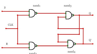
module srflipflop(q,qbar,s,r,clk);

input s,r,clk;

output reg q,qbar;

wire x,y;

nand g1(x, s,clk);

nand g2(y,r,clk);

nand g3(q, qbar,x);

nand g4(qbar,q,y);

endmodule


Behavioral Level Modelling

module srflipflop(q,qbar,s,r,clk);

input s,r,clk;

output reg q,qbar;

always@(posedge clk)

begin

case({s,r})

2'b00: begin q<=q; end

2'b01: begin q<=0; end

2'b10: begin q<=1; end

2'b11: begin q<=z; end

endcase

end

endmodule

Verilog Code for JK Flipflop


Gate Level Modelling

module jkflipflop(j,k,clk,q, qbar)

input j,k,clk;

output reg q,qbar;

wire x,y;

nand g1(x, j, qbar, clk);

nand g2(y, k, q, clk);

nand g3(q, qbar, x);

nand g4(qbar,q,y);

endmodule

Behavioral Level Modelling

module jkflipflop(j,k,clk,q)

input j,k,clk;

output reg q;

always @(posedge clk)

begin

case({j,k})

2'b00: begin q<=q; end

2'b01: begin q<=1; end

2'b10: begin q<=0; end

2'b11: begin q<=~q; end

endcase

end

endmodule

Verilog code for Full Subtractor

Diff = a^b^c

Borrow = (~(a ^ b) & c) | ((~a )& b)


Gate Level Modelling

module fullsubtractor(d,b,x,y,z);

input x,y,z;

output d,b;

wire p, q, r, s, t;

xor g1(p, x,y);

xor g2 (d,p,z);

not g3(q,x);

and g4(r, q,y);

not g5(s,p);

and g6(t,s,z);

or g7(b, t, r);

endmodule


Data Flow Level Modelling

module fullsubtractor(d,b,x,y,z);

input x,y,z;

output d,b;

assign d = x^y^z;

assign b = (~(x ^ y) & z) | (~x & y);

endmodule


Behavioral Level Modelling

module fullsubtractor(d,b,x,y,z);

input x,y,z;

output reg d,b;

always @ (x,y,z)

begin

case({x,y,z})

3'b000: begin d = 0; b= 0; end

3'b001: begin d = 1; b= 1; end

3'b010: begin d = 1; b= 1; end

3'b011: begin d = 0; b= 1; end

3'b100: begin d = 1; b= 0; end

3'b101: begin d = 0; b= 0; end

3'b110: begin d = 0; b= 0; end

3'b111: begin d = 1; b= 1; end

endcase

end

endmodule

Verilog code for Half Subtractor


 Diff= a^b

Borrow = (~a)b


Gate level Modelling

module halfsubtractor(d,b,x,y);

input x,y;

output d,b;

wire z;

xor g1(b,x,y);

not g2(z,x);

and g3(d,z,y);

endmodule


Data Flow Modelling

module halfsubtractor(d,b,x,y);

input x,y;

output d,b;

assign b= x^y;

assign d = ~x&y;

endmodule


Behavioral Level Modelling

module halfsubtractor(d,b,x,y);

input x,y;

output reg d,b;

always @(x,y)

begin

case({x,y})

2'b00: begin d= 0; b=0; end

2'b01: begin d= 1; b=1; end

2'b10: begin d= 1; b=0; end

2'b11: begin d= 0; b=0; end

endcase

end

endmodule

Verilog code for Full Adder


Sum = a^b^Cin
carry = ab | bc | ac


Gate Level Modelling

module fulladder(a,b,cin,s,cout);

input a, b, cin;

output s, cout;

wire x,y,z;

xor g1(x,a,b);

and g2(y,a,b);

and g3(z, x,cin);

xor g4(s, x,cin);

or g5(cout, y, z);

endmodule


Data flow modelling

module fulladder(a,b,cin,s,cout);

input a, b, cin;

output s, cout;

assign s= a^b^cin;

assign cout = (a&b) | (cin&a) | (cin&b);

endmodule


Behavioral level Modelling

module fulladder(a,b,cin,s,cout);

input a, b, cin;

output reg s, cout;

always @(a or b or cin)

begin

case ({a,b,cin})

3'b000: begin s= 0; cout=0; end

3'b001: begin s= 1; cout=0; end

3'b010: begin s= 1; cout=0; end

3'b011: begin s= 0; cout=1; end

3'b100: begin s= 1; cout=0; end

3'b101: begin s= 0; cout=1; end

3'b110: begin s= 0; cout=1; end

3'b111: begin s= 1; cout=1; end

end case

end

endmodule

Thursday 20 January 2022

Verilog Code for Half Adder


Gate Level Modelling


module Halfadder(a,b,s,c);

input a,b; 

output s,c; 

xor g1(s,a,b); 

and g2(c,a,b);

endmodule


Data Flow Level Modelling 

module Halfadder(a,b,s,c); 

input a,b; 

output s,c; 

assign s = a ^ b; 

assign c = a & b; 

endmodule 


Behavioural Flow Level Modelling 

module Halfadder(a,b,s,c); 

input a,b; 

output s,c; 

always @(a or b) 

begin 

case ({a,b}) 

2'b00: begin s = 0; c = 0; end  

2'b01: begin s = 1; c = 0; end 

2'b10: begin s = 1; c = 0; end 

2'b11: begin s = 0; c = 1; end 

endcase 

end 

endmodule

Verilog Code for Universal Shift Register

  Universal Shift Register module universalshift (clr,clk,sel,in,out); input clr,clk; input [1:0]sel; input [3:0]parin; output reg[3:0]out; ...